Introduction: When the analog signal changes slowly (<50Hz) (measurement of temperature/displacement/flow, etc.), you can choose a smaller bandwidth and low-frequency response isolation amplifier: ISO EM UPOM (M for low-frequency response) series products. In the high-frequency change (>2KHz) occasions (measurement speed/PWM control of switching power supply, etc.), high and low frequency response isolation amplifiers can be selected: ISO EM UPOH (H for high frequency response) series products. In addition to high frequency response and low frequency response environment, large Most industrial sites choose conventional frequency response products: ISO EM APO. Where there is spatial interference (high frequency/high current load) to the site environment, opto-isolated amplifiers: ISO U(A)-PO series should be selected.
Overview: The analog signal isolation amplifier (also known as analog isolation transmitter) input and output between industrial field sensors, PLC/FCS/DCS, and instrumentation belongs to the category of analog signal conditioning. The analog signal isolation amplifier can effectively protect the control loops at all levels, eliminate or reduce the impact of environmental noise on the test circuit, suppress the interference of the public ground, the frequency converter, the solenoid valve and the surge pulse to the equipment, and at the same time have the signal voltage limit for the lower equipment, Choke function. It is a reliable protective device for transmitters, instruments, frequency converters, solenoid valves, PLC/DCS input and output and its communication interface. For some industrial sites with harsh environments, the control system is intricate, high temperature, vibration, humidity and interference signals coexist, so the input and output analog signals are amplified, converted, and remotely transmitted through the isolation amplifier, and each system loop is completely isolated. It is indeed today's automated control. One of the effective measures against interference in the system.
The so-called bandwidth (band width) is also called bandwidth, which refers to the amount of data that can be transmitted at a fixed time, that is, the ability to transmit data in the transmission pipeline. In digital equipment, bandwidth is usually expressed in bps, which is the number of bits that can be transmitted per second. In analog equipment, bandwidth is usually expressed in cycles per second or hertz (Hz). The bandwidth of a signal refers to the frequency range occupied by the various frequency components contained in the signal.
Frequency response is abbreviated as frequency response, which is used in electronics to describe the difference in the processing capabilities of an instrument, PLC, and other equipment for signals of different frequencies. Like distortion, this is also a very important parameter index.
The test method of the bandwidth index is as follows. Add a frequency-adjustable sine wave analog signal to the input terminal, and the maximum frequency range where the output terminal can stably follow the input terminal signal is the bandwidth. What is the engineering significance of the bandwidth index of the industrial signal isolation amplifier? How do we understand the "bandwidth" in the application? The bandwidth index reflects the response speed of the isolation amplifier to changes in the input signal. The larger the bandwidth, the faster the response speed of the isolation amplifier to signal changes; the smaller the bandwidth, the less sensitive the isolation amplifier is to the instantaneous changes of the input signal. In some cases, it means that the anti-interference ability is stronger.
The working principle of isolation amplifiers and isolation transmitters is to first modulate standard signals sent and received by sensors, instrumentation, PLC, or special signals such as temperature, displacement, frequency, and speed through semiconductor devices, and then modulate them by light sensing or magnetic sensing. The device performs isolation conversion and transmission, and then performs demodulation to restore the original signal with the same accuracy and linearity or transform it into other signals. At the same time, the working power of the signal before and after isolation is isolated to ensure the signal input, signal output and auxiliary power supply. That is, the three isolations between the signal, power supply, and ground before and after conversion. Analog signal isolation amplifiers and isolation transmitters belong to a device in the classification of industrial instrumentation and sensors. Their main functions are the isolation, amplification, conversion and transmission of analog quantities, so there must be signal bandwidth and frequency response. Technical indicators.
Industrial field signal transmission interference processing reference plan (the inverter anti-EMC interference special isolation amplifier):
There are systems with EMC interference sources such as frequency conversion control equipment, high-power electromagnetic starting equipment, and GPS high-frequency signal wireless transceivers in the industrial field. It is necessary to analyze and determine interference signal processing solutions according to the characteristics of different interference sources and system control signals.
1. Interference on the output analog signal of the sensor
Installing the ISO series analog signal isolation amplifier at the sensor output can effectively solve the attenuation and EMC interference in the analog signal transmission process, and enhance the stability and reliability of the display control system. Analog signal isolation amplifier for inverter anti-EMC interference: ISO EM UPOM series, which is equipped with input signal interference suppression filter circuit and output interference harmonic absorption circuit inside the IC to enhance the anti-EMC electromagnetic interference and high-frequency signal spatial interference function . It is especially suitable for occasions where there are frequency conversion control equipment, high-power electromagnetic starting, and GPS high-frequency signal wireless transceiver devices on site.
2. Spatial interference caused by high-frequency signal radiation
Each control system and equipment are equipped with metal shielding boxes (different metal components used in different frequency ranges) and the shell is reliably grounded. The signal communication transmission line uses twisted-pair shielded cables.
3. RS232/RS485 remote communication line interference
Install a DC-DC isolation module power supply on the RS232/RS485 communication interface to directly isolate the communication power supply from other power supplies. Signal communication transmission lines should also use twisted-pair shielded cables (shield layer is grounded).
4. Interference in the power supply circuit of the system
The presence of high-current thyristors, frequency conversion control equipment, and high-power electromagnetic starting devices on site will have a distortion effect on the power supply parameters of the power supply system. Through the power circuit, the interference signal will enter the various control devices on the scene. Therefore, first of all, it is necessary to make sure that each device on the site is well grounded, and the power supply of each device should be equipped with a matching power filter (low-pass EMI filter or suppression reactor).
Bandwidth and frequency response of analog signal isolation amplifier isolation transmitter industrial field technical index selection application reference:
1. When the analog signal changes slowly (<50Hz) (such as measuring temperature, pressure, displacement, flow, etc.), an isolation amplifier with a smaller bandwidth and low frequency response can be selected: ISO EM U(A)-POM series products ( M: Represents low frequency sound). Therefore, in the frequency converter control system, in order to suppress and isolate EMC interference, often choose: ISO EM U-P-O-M series isolation amplifier.
2. When the analog signal has a high changing frequency (>2KHz) (such as measuring speed, adjusting high-speed electronic switches, PWM control of switching power supply, etc.), in order to ensure the integrity and reliability of the collected data, high bandwidth, high and low frequency response is often used. Isolation amplifier: ISO EM U(A)-POH series products (H: means high frequency response).
3. Most systems other than high-frequency and low-frequency response environments choose conventional frequency response (2K) products: ISO EM A-P-O or ISO EM U-P-O series.
4. Photoelectric isolation amplifier: ISO U(A)-P-O-M series can be selected for occasions where there is strong magnetic space interference (high-frequency electromagnetic and high-current load) to the on-site environment.
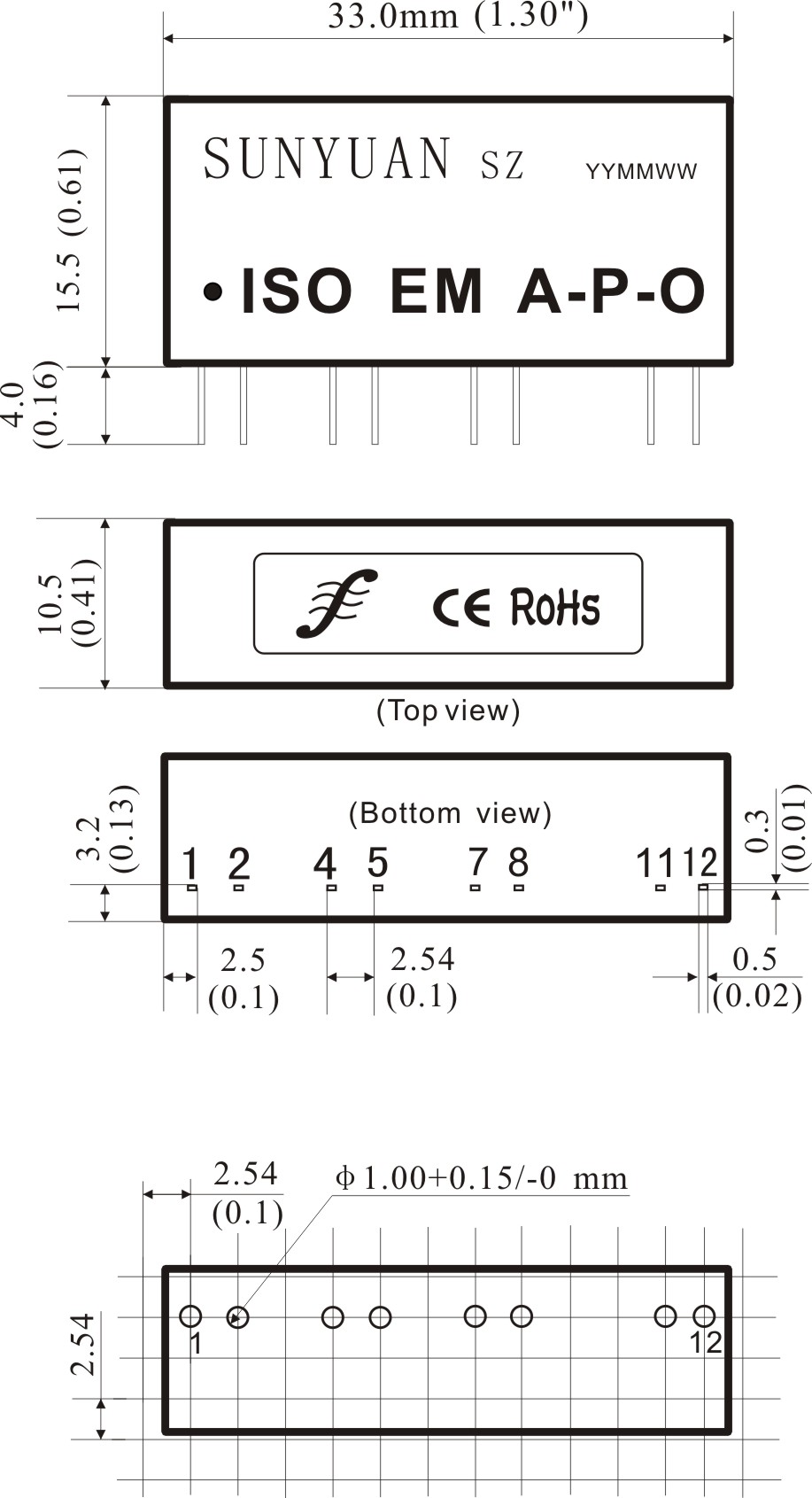
Signal isolator/isolation amplifier/isolation transmitter IC outline size and PCB layout size reference (SIP12 Pin)
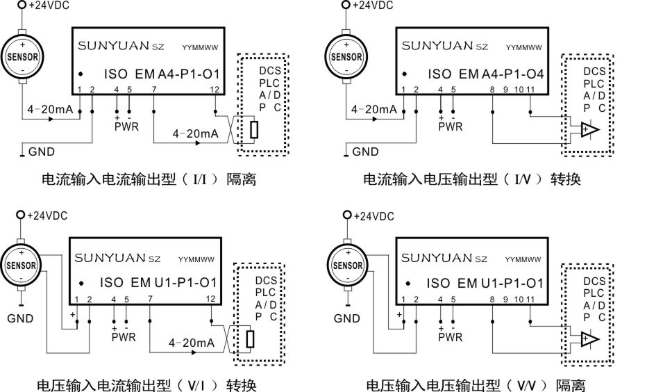
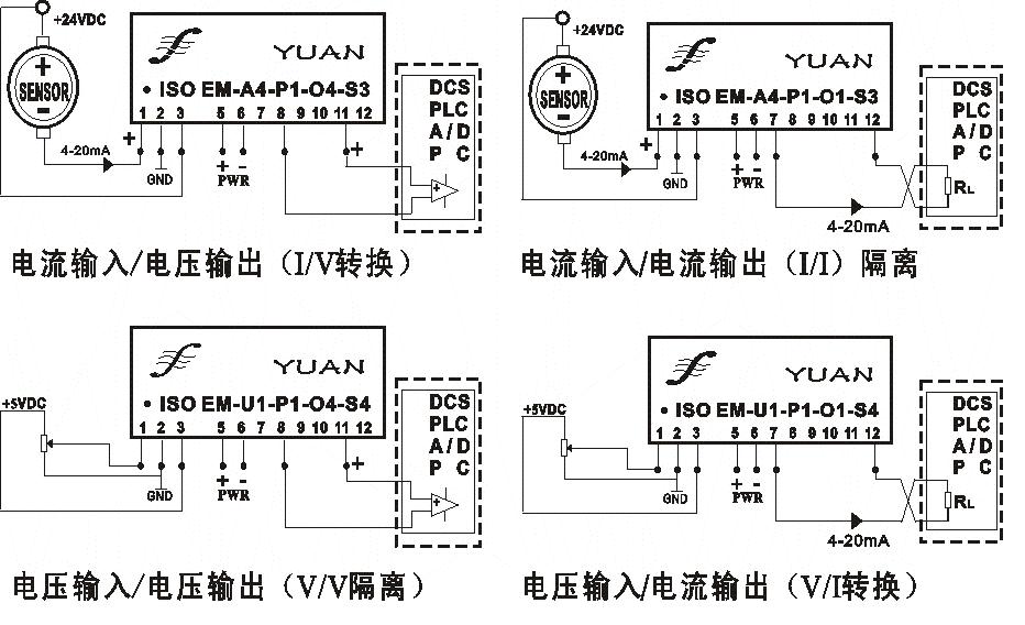
Isolation amplifier isolation transmitter IC, ISO EM series typical application wiring diagram (ISO EM A-P-O / ISO EM U-P-O)
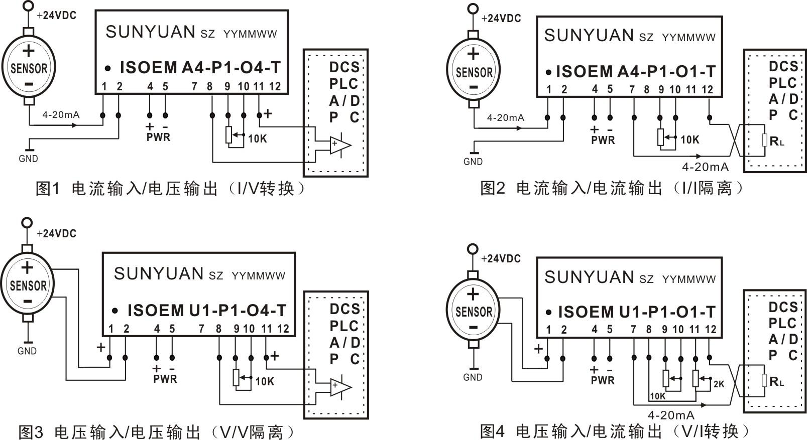
Zero point and gain adjustable isolation amplifier IC, ISO EM-T series typical application wiring diagram (ISO EM A-P-O-T / ISO EM U-P-O-T)
Zero point and gain adjustable isolation amplifier IC, ISO EM-T series typical application wiring diagram (ISO EM A-P-O-T / ISO EM U-P-O-T)