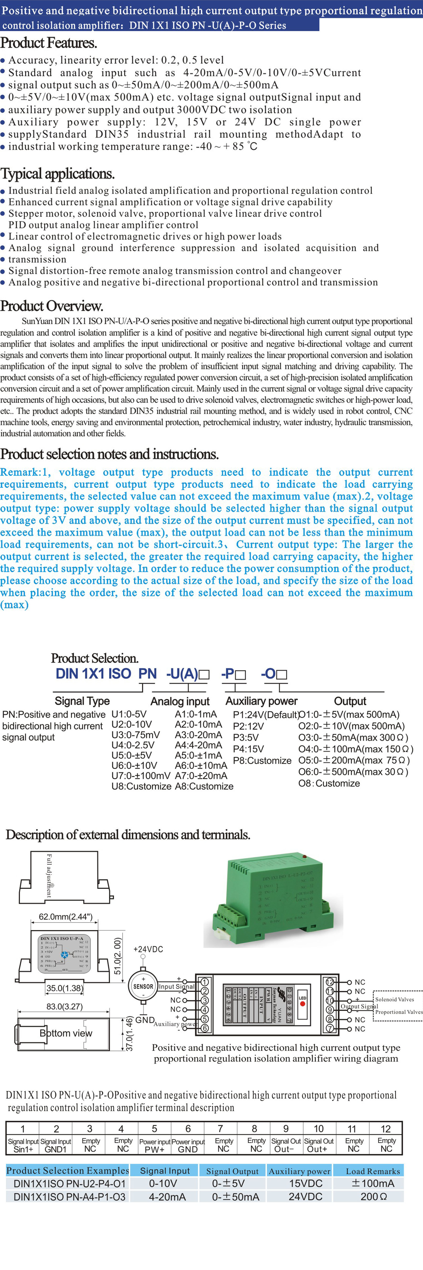
SunYuan proportional regulation control high-power isolation amplifier is composed of various analog isolation amplifier circuits and high-precision power amplifier circuits, which is mainly used in proportional valves, precision temperature controllers, electric flow control valves, precision solenoid displacement gauges, and other occasions that require precision drive control of high-power loads. The product adopts standard DIN35 rail mounting mode, which can isolate and power amplify the analog output of PWM/4-20mA/0-10V/0-5KHZ/0-5KΩ/RPM/displacement/pressure/flow/temperature and other kinds of sensors, transmitters and PLC outputs, and output linear and high-precision analog large driving current such as 0-100mA/0-500mA/0-1A/0-2A/0-3A.
The products are designed with small size and simple structure, low cost and high reliability, suitable for - 40 ~ + 85 ℃ industrial site. Widely used in electro-hydraulic proportional valves, CNC machine tools, robots, engineering vehicles, shipbuilding, petrochemical, water industry, hydraulic transmission, industrial automation and other fields.
Input Signal Classification Description
1、Z-W : RTD temperature signal input
RTD type Z1: Pt100 Z2: Pt10 Z3: Cu100 Z4: Cu50
Input temperature range W1: -20-100°C W2: 0-100°C W3: 0-150°C W4: 0-200°C W5: 0-400°C W8: User-defined
2、PWM : Pulse Width Modulation Signal Input
D1: 50Hz-99Hz PWM signal input D2: 100Hz-0.9KHz PWM signal input
D3: 1KHz-9KHz PWM signal input D4: 10KHz-19KHz PWM signal input
D5: 20KHz-50KHz PWM signal input D8: User defined
3、AC : AC signal input
Input rated voltage value AC : 0~1Vrms
4、R : Electronic ruler, displacement signal input
R1: 0-50Ω R2: 0-100Ω R3: 0-200Ω R4: 0-500Ω
R5 : 0-1KΩ R6 : 0-2KΩ R7 : 0-5KΩ R8 : User-defined R9 : 0-10KΩ
5、RMS : True RMS signal input
200RMS: 0-200mV; 1000RMS: 0-1000mV
6、F : Frequency signal input
F1: 0-1KHz F2: 0-5KHz F3: 0-10KHz F8: User-defined
Product Selection Example
Example 1: Input/output isolated type; Input signal: 4-20mA; Output signal: 0-3A, max 4.5Ω; Auxiliary power supply: 24VDC
Model No.: DIN 1X1 ISO A4-P-3A
Example 2: Non-isolated input/output type; Input signal: 0-1KHz; Output signal: 0-2A, max 10Ω; Auxiliary power supply: 24VDC
Model No.: DIN 1X1 SY F1-P-2A
Potentiometer Adjustment Instructions

Users can tell us the field application parameters before ordering the product, so that it can be adjusted and sealed according to the technical requirements at the factory.
As shown in the figure: four multi-turn potentiometer knobs on the side of the shell, clockwise rotation adjustment decreases, counterclockwise for increasing.
Zero calibration adjustment: given the minimum input signal, adjust the potentiometer knob to make the output current zero.
Fullness calibration adjustment: Given the maximum input signal, adjust the potentiometer knob to maximize the output current.
Rising Edge Response Time: Connect the oscilloscope to both ends of the output load, adjust the potentiometer and observe the rising edge time of the waveform.
Falling edge response time: connect the oscilloscope to both ends of the output load, adjust the potentiometer and observe the falling edge time of the waveform.
Typical Application Examples
Application 1: Direct input of sensor-transmitter signals such as 0-10V/PWM/0-10K/Pt100/0~1Vrms/RMS.
In this application mode, the signal input, signal output and auxiliary power supply are 3000VDC triple isolated.

Application 2: Application mode in which the module's own distribution output of 10VDC is used with an external resistor or potentiometer to form an electronic ruler or bridge input.
In this application mode, the ground (GND) of the signal input and the ground (GND1) of the power distribution output are connected to a common ground. Therefore, the signal input and signal output are 3000VDC isolated from each other.
